

The check tells you how each sheet will strip on your machine. Your die maker still designs the female board and any stripping tool, and places the nicks.
With a pin matrix, stripping pins on bars or in a plate of holes push each waste piece through a female stripping board. Describe it once on the die-cutter; imposition and box quotes check and price their dies against it.
What the pin matrix does#
The waste left after cutting splits into parts:
- The skeleton is the connected waste that carries the blanks out of the stripper. It is never stripped. Its narrowest strip between two knives is the skeleton bar: too thin and it tears.
- Front waste and rear waste are the strips in front of the first knife and behind the last one. The grippers or a front-waste separator take the front; the machine's rear-waste stripping takes the rear.
- Every other piece is a waste piece: a pocket between blanks, a window slug, an edge piece cut free. Pieces too small to pin are chips: counted and reported, never dropped.
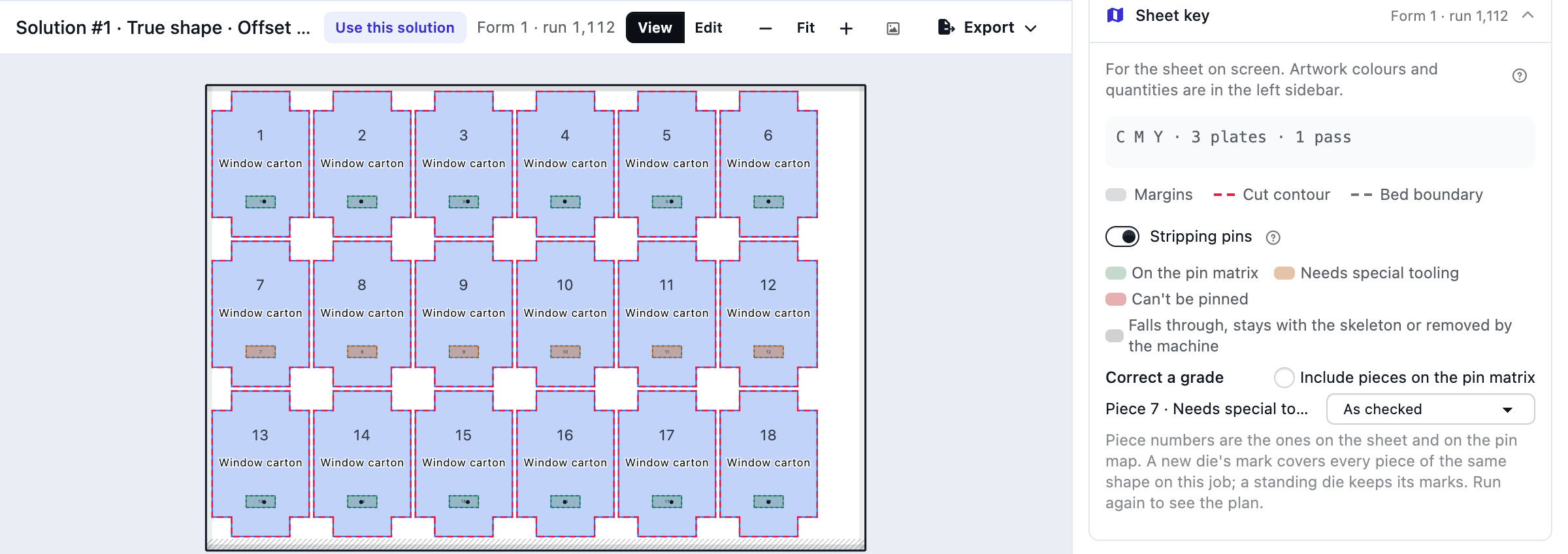
Each waste piece gets one grade: on the pin matrix, needs special tooling, falls through, stays with the skeleton, removed by the machine or can't be pinned.
Set up the die-cutter#
Open the die-cutter in Equipment and choose How it strips waste: no stripping, stripping tools made for each die (what every die-cutter did before), or a pin matrix. A rotary die-cutter can't use a pin matrix: rotary dies eject waste with rubber. Saving a die-cutter as rotary clears its pin-matrix settings.
Every platen die-cutter, whatever the method, takes Gripper margin (mm), Narrowest skeleton bar it runs (mm), Allow common cut on new dies, Standard lead to the first knife (mm) (at least the gripper margin), Operator side (it labels the pin map) and off-line hand stripping: Hand stripping per waste piece (min per 1,000 sheets), Hand stripping cost per hour and Hand stripping price per hour. Empty means no rule.
A pin matrix adds four groups:
- Grid. Leave Pin grid pitch (mm) empty for bars and holders, where a pin can go anywhere in the area. With a pitch, pins go only on the holes: Grid pattern, First grid hole from the centre line (mm), First grid hole from the lead edge (mm). The Usable pin area (mm) is centred on the centre line and measured from the lead edge.
- Stripping pins. Stripping-pin needle (mm) (typical 1.5–4 mm, check your machine), Clearance from the knife (mm) (typical 3–5 mm, check your machine), Lower pins, Lower pin body (mm) (typical 8–15 mm, check your machine), Smallest waste a lower pin holds (mm), Two stripping pins when a piece is longer than (mm), Pin bars the frame takes with Holder reach from the bar (mm) (free positions only), Fit new dies to the pin grid and the board setting (see Cost and time).
- Waste. Pieces this small fall through (mm), Edge pieces this small stay with the skeleton (mm), Waste chips under (mm²) (empty: 1 mm²), Suggest breaker knives above (mm), Front waste and Rear waste.
- Time. Pin-matrix setup per die (min), Setup per stripping pin (min) and Setup per pin bar (min).
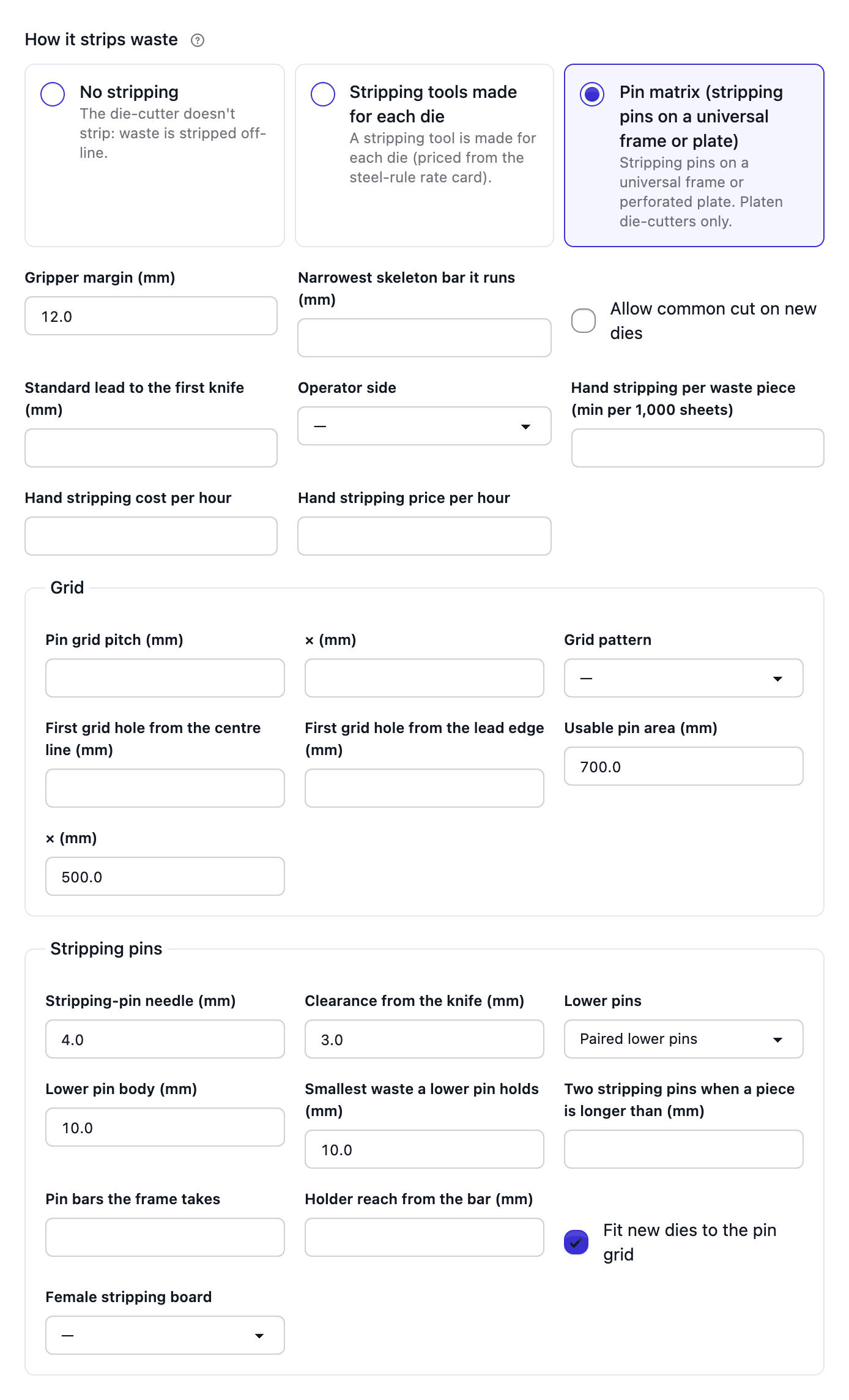
No pin sizes, times or prices are shipped: every value is yours. Positions run across from the centre line and along from the lead edge, the sheet fed centred, print side up, on the press's lead edge. The saved page previews the sheet, gripper band, pin area and grid at true scale.
How waste is graded#
A stripping pin needs a spot in the piece at least the clearance plus half the needle from every knife. A piece outside the usable area, or with no such spot, can't be pinned, unless it is small enough to fall through. On a hole grid the pin must sit on a hole, or the piece needs special tooling; so does a piece too close to another pin for two lower pin bodies, or too small for the smallest-waste size. Bigger pieces claim their spot first.
A piece longer than the two-pin length gets two stripping pins. Edge pieces no bigger than the nick size stay with the skeleton. Front waste stays with the grippers (or goes to the separator) and rear waste is removed by the machine, unless you strip it with pins.
The check also raises Needs special tooling, Can't be pinned, Thin waste tips (a tip that may tear), Waste chips, Thin skeleton bars, Cuts in the gripper and Breaker knives suggested: long waste gets breaker knives suggested, with the piece and pin counts both as cut and with the breakers. With a bar count, pins are grouped into bar rows; more rows than the frame takes raises Too many pin bars.
Correct a grade#
The check doesn't see nicks. Switch on Stripping pins in the viewer's key and, under Correct a grade, mark a piece Nicked to the skeleton, Falls through, Stripped by hand or Needs a stripping tool, then run again. The list shows the pieces off the pin matrix; switch on Include pieces on the pin matrix to mark one the check placed on it, such as a piece the die maker nicked. Pieces are numbered on the sheet as on the pin map, and pointing at a piece shows its number and grade. A mark on a standing die stays with the die, on every job; its window slugs, and a die estimated from its stations, are marked like a new die's. A mark on a new die covers every piece of the same shape on the job, as it does under Plan freely.
Imposition on a pin matrix#
New dies keep their first knife clear of the gripper margin, or at the standard lead. Besides the shop's knife gap, a die is offered at the skeleton bar when that is wider, and at gap 0 when common cut is allowed and the die-cutter doesn't blank (Common cut can't blank otherwise). Each is its own option ("New 21-up · common cut"), ranked by total cost. On a hole grid, Fit new dies to the pin grid on the Tooling card moves a new die up to one pitch, in 0.5 mm steps within the job's margins, so more pieces land on holes ("moved 3 mm onto the pin grid"); with a standard lead, sideways only. Its ups never change. Above 400 stations the move is skipped (Grid fit skipped).
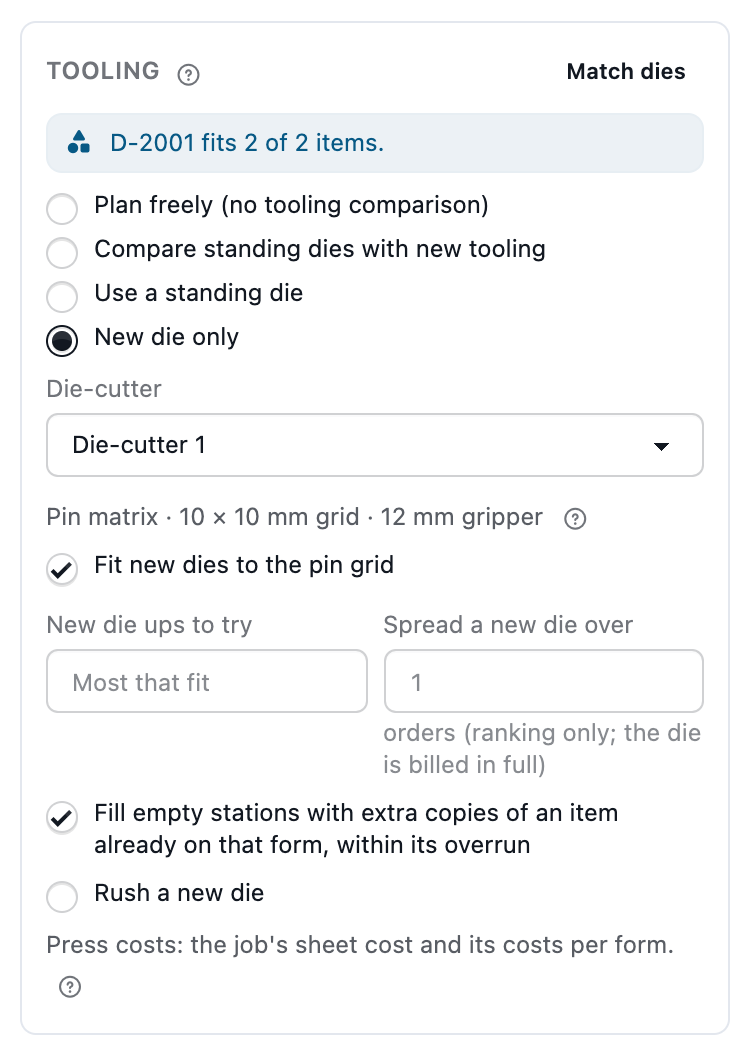
Standing dies are checked and never changed. Their waste comes from the die file. A die imported earlier is estimated from its stations (Waste estimated), and a stations edit marks it Waste out of date: attach its file again to check it exactly. Its page lists how it strips on each pin-matrix die-cutter it mounts on. Dies planned by today's method aren't checked: they keep a stripping tool (Pins not checked).
Under Plan freely, a job whose Die-cutter is set to a pin-matrix machine is checked after the run: report only, the plan never changes. Box quotes check a new die at the line's own ups and gutter, never offering other gaps or moving it, and a die on hand as above.
Cost and time#
Each die takes the cheapest priced plan:
- Pins: the pin setup per die mount, a female stripping board, and off-line hand stripping for what the pins can't take.
- Pins and a lower pin unit, when pieces need special tooling and a unit is on hand or priced.
- Stripping tool: the stripping cost from the rate card and the die-cutter's stripping setup.
- None: Nothing to strip.
Female stripping board says whether a board is made for each die. It costs a base plus an amount per opening, from the steel-rule rate card. A Female stripping board or Lower pin unit on hand as a companion of the die costs nothing. To choose, tooling is spread over Spread a new die over orders; setup and hand time count on every run. Hand stripping is off-line labour at its own rate, never machine time. A plan missing an input is shown but never chosen over a priced one: Pin setup not set, Female board not priced. Hand stripping at the die-cutter's rate says Hand at machine rate; pieces left to hand show Hand stripping. A die-cutter that doesn't strip prices window slugs as hand stripping, or says Off-line stripping not priced, on new dies, standing dies and today's method alike. Without a pin matrix a standing die needs a stripping tool only when it is marked for one, as before.
Solutions show a chip per die ("Pins 33/33", "2 by hand", "Stripping tool"); the Report adds a stripping line per die, the plans compared at cost as below, and Hand stripping (off-line).
Example (example rates, never defaults): 5,000 sheets, spread over 3 orders, die-cutter $120 an hour. Two pieces take pins and one sliver is stripped by hand at 3 min per 1,000 sheets at $40 an hour. Pins: board $40 ÷ 3 = $13.33, setup 10 + 2 × 0.25 = 10.5 min = $21.00, hand 15 min = $10.00, so $44.33. Stripping tool: $150 ÷ 3 = $50.00 plus 20 min = $40.00, so $90.00. The pins win.
Pin map and exports#
Stripping pins in the viewer's key tints each piece by grade and shows its pins.
The imposed PDF carries a Stripping layer that never prints. The export menu adds:
- Pin map (PDF), one page per die, at 1:1 when the sheet fits A3 or tabloid: gripper edge, operator and drive
side (with the operator side set), print side up, the centre line, numbered pieces and pins, grid labels such as
C30 R39, a 100 mm scale bar and "Same lead edge as the press, print side up, sheet centred". Measure the scale bar before setting pins. - Pin list (CSV):
die, form, piece, class, grade, reason, pin, x_mm, y_mm, side, grid_col, grid_row, bar, x from the centre line and y from the lead edge, to 0.1 mm. - Pin DXF, one per die, in mm with layers
KNIFE,WASTEandSTRIPPING_PINS. There is no CF2 pin line.
Limits#
- Platen die-cutters only, one matrix per machine.
- Nicks aren't detected: waste pieces are assumed not nicked, blanks nicked to the skeleton. Mark the exceptions.
- Bars and holders are only laid out when the bar count is set.
- Blanking is checked only through the common-cut rule.
- One set of values per machine, whatever the board or caliper.
- Speed lost to hard stripping isn't modelled.
- Chips are reported, not stripped.
- Without a pin matrix, only window slugs count for off-line stripping.
- No maker publishes a pin pitch, and breaker knives are suggestions.
- The die maker designs the female board and any stripping tool.